Setup
In order to determine the sound of rain, a proper setup is necessary. To simulate the sound of rain, we wanted the droplet to fall down from as high as possible. Just like real rain falls from clouds kilometers up in the air. Unfortunately for us, the ceiling was the limit. We could let the droplet fall down from two meters high. This is not high enough to create closed cavities, but high enough to create the characteristic sound of rain.
With this small restriction we had to start building the setup. We started with placing the hydrophone directly underneath the position of impact. This way, the sound we measure will contain the least side noise that could interfere with our wanted sound. The hydrophone should be as close as possible to the cavity that is created by the impact of the droplet, but not so close that the cavity makes contact with the hydrophone. To analyse the sound that is produced by the droplet's impact, we used a amplifier. The amplitude of the direct sound is not great enough to analyse, so amplifying is necessary. Further, we used a oscilloscope to transfer the signal from the amplifier to the computer, the computer is not able to analyse it directly.
Now we can "hear" the impact of the droplet clearly, we want to see what happens when the droplet hits the water. This way we could be able to see the phenomena that produce the sound. To have a good look at the impact, we used a high speed camera. Using a high speed camera gives us the ability to see very small changes in the water surface over time. This makes it a lot easier to correlate the sound to what we observe. We set the camera to take 200.000 images per second, this also means that a very small amount of light of the surrounding light ends up on the image. To get images that are bright enough to analyse, we had to use a very bright light source to illuminate the water container. We placed the source behind the water container, so the light would go through the container and into the camera. Only this direct light is too bright, so we used a plate of semi transparent plastic. This plastic plate did the trick for us.
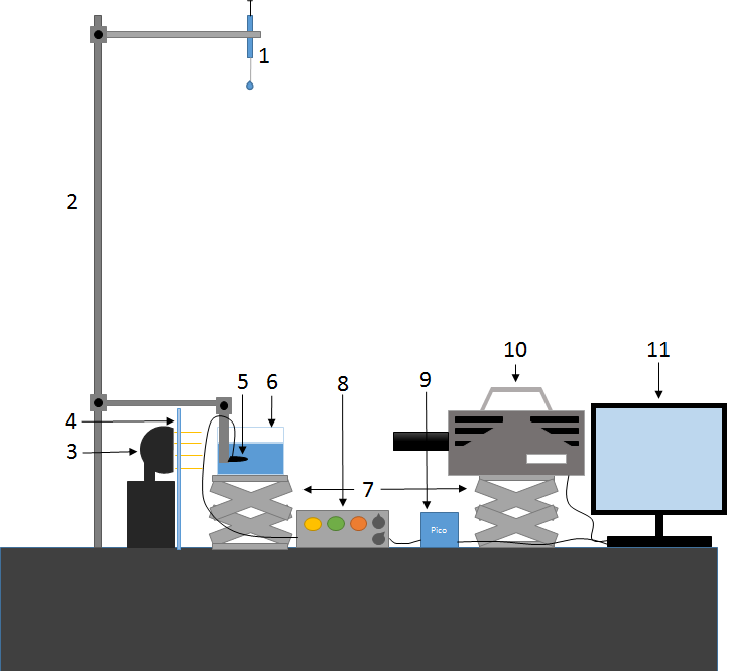
- Syringe
- Holding elements
- Light source
- Transparent plate
- Microphone
- Transparent container
- Standards
- Amplifier
- Oscilloscope
- High speed camera
- Computer
Equipment
This list contains the most detailed description of all the equipment we used to perform this experiment.
- High speed camera: Fastcam SA-X2 photron limited
- Camera lens: Carl zeiss macro planar t* f100 workdist0.44_inf max imrat 1:2 max ap 1.8 cammount Nikon f
- Light source: Hella flood lights
- Syringe: BD Plastipak 1ml syringe
- The following needles:
- Terumo needle; 18G x 2”, 1.2 x 50 mm
- Terumo needle; 22G x 1.5”, 0.7 x 40 mm
- Terumo needle; 24G x 1”, 0.55 x 25 mm
- Terumo needle; 26G x 0.5”, 0.45 x 12 mm
- BD Microlance 3; 30G x 0.5”, 3 x 13 mm
- Charge amlifier: Vibrometer sa Firbourg, type; TA-3/D
- Hydrophone:
- Oscilloscope: Picoscope 5243B
- Working table: Smart table UT 2, Newport Stabilizer High Performance Laminar Flow Isolator I-2000 series
- Acrylic glass container
- Semi transparent plastic
- Lifters
- Ladder
- building elements